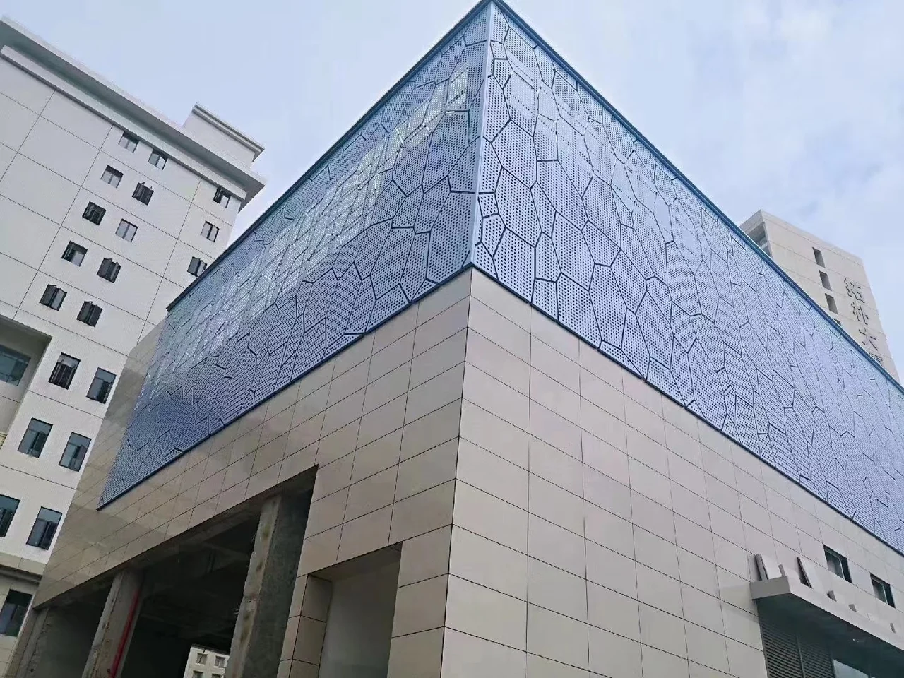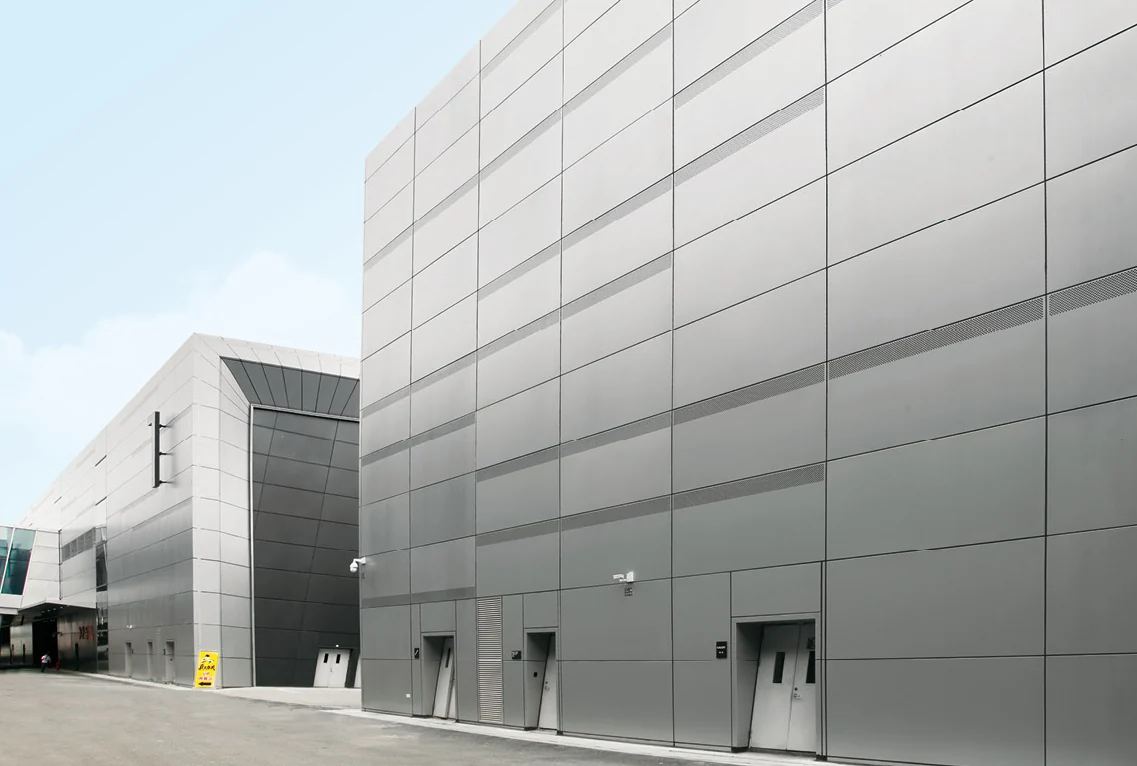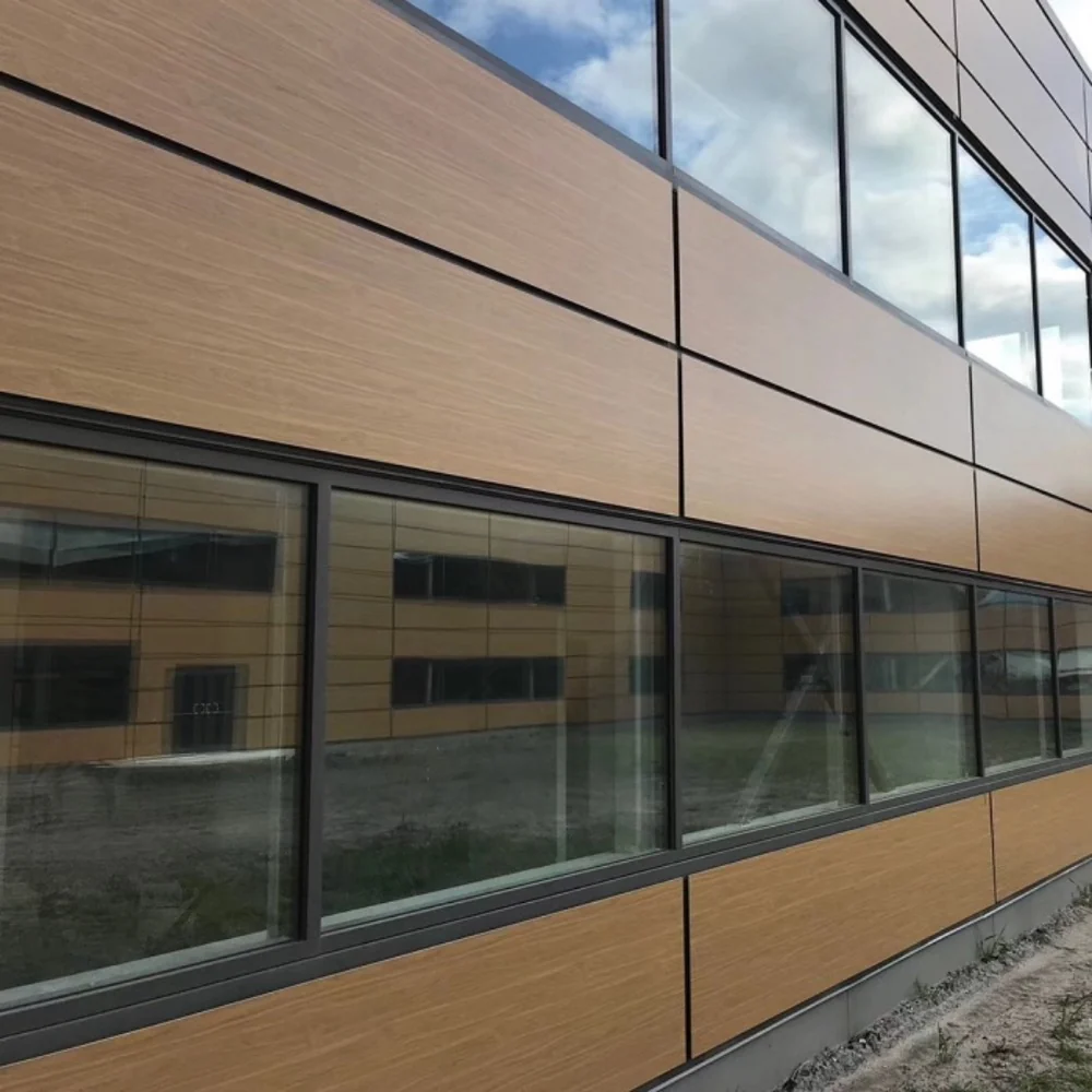

Compare honeycomb and corrugated-core aluminum panels by their complete section: skins, core, bond, edge closure and fixing detail. Overall thickness alone does not establish stiffness, allowable span or fire performance. This guide turns a vague panel description into a layer schedule and a like-for-like purchasing comparison.
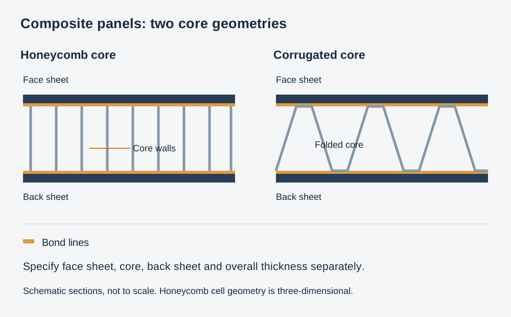
How the two constructions differ
| Item | Aluminum honeycomb panel | Corrugated-core panel |
|---|---|---|
| Internal geometry | Hexagonal aluminum cells between face and rear sheets | Corrugated aluminum reinforcement bonded to the face construction |
| Overall thickness options | 12, 15, 20, 25 and 30 mm | 6 and 10 mm |
| Section to specify | Face sheet, core, rear sheet, adhesive and edge construction | Face sheet, corrugation geometry, bonding and any rear closure |
| Connection options | Hook-on or angle-bracket arrangement | Hook-on or angle-bracket arrangement |
| Drawing priority | Layer schedule and load transfer at edges and fittings | Corrugation direction, support positions and edge detail |
Separating the face sheets with a core can increase bending stiffness without filling the entire section with solid aluminum. The face sheets and core work together through the bond. That makes the adhesive connection, core properties and local fixing design important, not incidental details hidden behind the decorative face.
Corrugation has a defined direction. Show that direction relative to the panel span and supports. Honeycomb also requires a specified core and orientation where relevant to the design; neither construction should be assumed to behave identically in every direction.
Read a layer schedule instead of ordering “15 mm honeycomb”
A useful schedule identifies each component. For example, a nominal 15 mm construction could be scheduled as 1.0 mm face + 13.2 mm core + 0.8 mm rear sheet. This is a worked specification example, not the standard construction of every 15 mm panel. The final manufacturing section must also define adhesive layers, finish and the finished-thickness tolerance.
Compare that with an alternative described only as “15 mm aluminum honeycomb.” Without the face, rear sheet and core entries, the two quotations are not yet comparable. The visible finish and overall depth can match while the concealed construction differs.
| Component | Information to record |
|---|---|
| Face and rear sheets | Alloy, temper, individual thicknesses and finish on each side |
| Core | Material, cell or corrugation geometry, thickness and relevant direction |
| Bond | Adhesive system and the preparation/bonding specification |
| Finished panel | Overall thickness, face size, edge closure and permitted tolerances |
| Fixings | Bracket or hook geometry, fastening location and supporting layout |
Check local fixings as carefully as the broad panel face
A light core occupies most of the panel depth. A fixing detail therefore needs to show where the load enters the panel: a folded edge, a reinforced zone, an insert or another designed connection. Specify that detail rather than positioning a screw on the face drawing and leaving the concealed connection unresolved.
At service openings, draw the exposed edge and any reinforcement or closure. A large cut-out can interrupt the original load path and leave the core exposed. Coordinate the opening and equipment support before the panel section and bonding work are finalized.

Compare two quotations line by line
| Field | Offer A | Offer B | Purchasing decision |
|---|---|---|---|
| Overall thickness | 15 mm nominal | 15 mm nominal | Same headline dimension only. |
| Face / core / rear | 1.0 / 13.2 / 0.8 mm | Not itemized | Request B’s layer schedule before comparing. |
| Core and bond | Product designations required | Product designations required | Record both; dimensions alone do not identify the bond or core. |
| Fixing detail | Drawing H-02 | “Standard brackets” | Obtain B’s connection drawing and compare it with the support layout. |
| Opening | Dimensioned light opening with edge closure | Not included | Price the same opening and closure before comparing totals. |
Offer A is better defined, not automatically better performing. Both still need the specified evidence for the panel, connection and intended use. The comparison makes omissions visible without assuming that the higher price, thicker-looking panel or larger face guarantees a stronger assembly.
Keep panel area and supplied quantity separate. Ten panels with finished faces of 1,200 × 600 mm have a combined face area of 7.2 m². That figure does not include spare panels, perimeter pieces, brackets or the cost of special openings. List those items explicitly to avoid comparing a complete package with bare panels.
Balance large modules against handling and access
Larger faces reduce the number of visible joints, but they also change the lifting, transport and replacement plan. Check the largest panel against delivery doors, lifts, turning spaces and the clear area available below the ceiling. Confirm how an individual panel is supported while its fixings are released.
The range includes dimensional limits up to 10,000 mm in length and 1,500 mm in width. Those limits are not a promise that any combination of length, thickness, finish and fixing can be ordered as one panel. Select the actual module after the section, support design and handling route have been reviewed.
Inspect the assembly in three separate ways
- Identity and dimensions: compare the supplied layer schedule, panel number, thickness, face dimensions and fittings with the approved order.
- Appearance and fit: inspect face alignment, edge finish, joints and trial assembly of critical adjoining panels.
- Specified performance: check that bond, structural, fire or other required evidence covers the supplied assembly and intended use.
Aluminum skins do not define the fire classification of a bonded panel. Adhesive, surface finish, core and complete construction belong in the relevant submission. Similarly, increasing overall thickness does not replace checking the proposed spans, supports and connection loads.
Follow the load through the sandwich
In a sandwich panel under bending, the separated face sheets and core have different structural roles. The bond transfers forces between them; the core supports the skins and carries shear. Increasing the distance between skins can improve stiffness, but it does not eliminate checks for skin instability, core shear, bond failure or local bearing at the supports.
Ask for the proposed support arrangement, loading direction and deflection criterion with any span submission. For a ceiling, the self-weight and service arrangement differ from an external facade subject to wind pressure and suction. Do not transfer a ceiling application span to a facade solely because the overall thickness is the same.
Inspect bonded panels without relying on appearance alone
A flat, clean face does not demonstrate bond integrity. Agree the production records and the relevant test or inspection method before manufacture. Where sample testing is specified, identify how the sample represents the supplied skin, adhesive, core and curing route. A casual tap on the face is not a substitute for an agreed acceptance procedure.
Pay particular attention to routed edges, inserts, service openings and corners. The detail should show how exposed core is closed, where fasteners obtain their resistance and how the skin remains supported next to an opening. Resolve moisture exposure and drainage for the intended use, rather than describing a sealed edge as automatically waterproof under every condition.
Review substitutions as a complete construction
- Compare individual skin thicknesses, not just total panel depth.
- Compare core geometry and material designation, including relevant orientation.
- Check adhesive compatibility, bonding controls and intended environmental exposure.
- Recheck inserts, edge reinforcement, brackets and fastener engagement.
- Confirm whether the revised assembly is covered by the required structural and fire evidence.
Record an accepted substitution on the layer schedule and the panel drawing together. The installation team should not discover a different edge or fixing zone after the replacement material has arrived.
Which information makes a quotation useful?
Send the layout, selected honeycomb or corrugated-core construction, layer schedule, face sizes, openings, fixing detail and finish sample. Identify access panels and the largest pieces separately. Ask suppliers to list deviations beside the proposed section, so a thinner face sheet or different edge detail is visible before the price comparison.