Specify a perforated aluminum panel in two parts: the hole geometry and the acoustic build-up, if sound absorption is required. This guide calculates square and staggered open area, deducts solid borders, and explains the report details needed to compare backed ceiling assemblies. Open area is a geometric percentage, not an acoustic rating.
Calculate open area from diameter and pitch
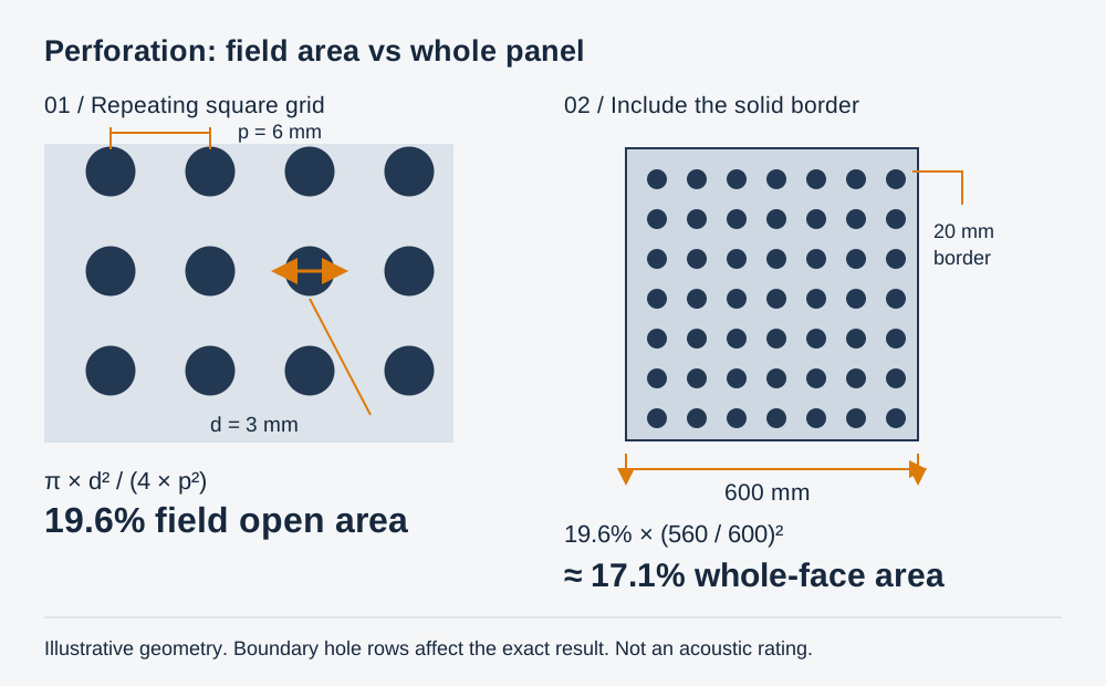
For circular holes on a square grid, the nominal open area of the perforated field is π × d² ÷ (4 × p²) × 100%, where d is hole diameter and p is centre-to-centre pitch. This is a geometric calculation for a repeating pattern, before solid borders or service openings are considered.
| Hole diameter d | Pitch p | Metal between holes p − d | Nominal field open area |
|---|---|---|---|
| 2 mm | 5 mm | 3 mm | 12.6% |
| 3 mm | 6 mm | 3 mm | 19.6% |
| 3 mm | 5 mm | 2 mm | 28.3% |
The last two patterns use the same hole diameter, but the tighter pitch gives substantially more open area and a narrower metal ligament. They will not have the same appearance or remaining sheet geometry. Whether either pattern is suitable also depends on material thickness, forming, border width and tooling.
For a regular 60-degree staggered arrangement, the corresponding formula is π × d² ÷ (2 × √3 × p²) × 100%, with p measured between nearest hole centres. A 3 mm hole on a 6 mm staggered pitch gives approximately 22.7%, not the 19.6% square-grid result. Always state the layout, not only “3 mm holes at 6 mm centres.”
Include solid borders in the panel-level calculation
Worked example: take a 600 × 600 mm face with a 20 mm solid border on all four sides. The perforated field is 560 × 560 mm, or 87.1% of the full face area. With the 3 mm / 6 mm square pattern above, the approximate open area over the whole face is 19.6% × 87.1% = 17.1%.
This calculation ignores partial hole rows at the pattern boundary and is therefore an estimate. The production drawing establishes the actual hole count. If a specification asks for “20% open area,” clarify whether that means the perforated field or the whole finished face; otherwise two proposals may use the same words for different panels.
Understand what the acoustic backing does
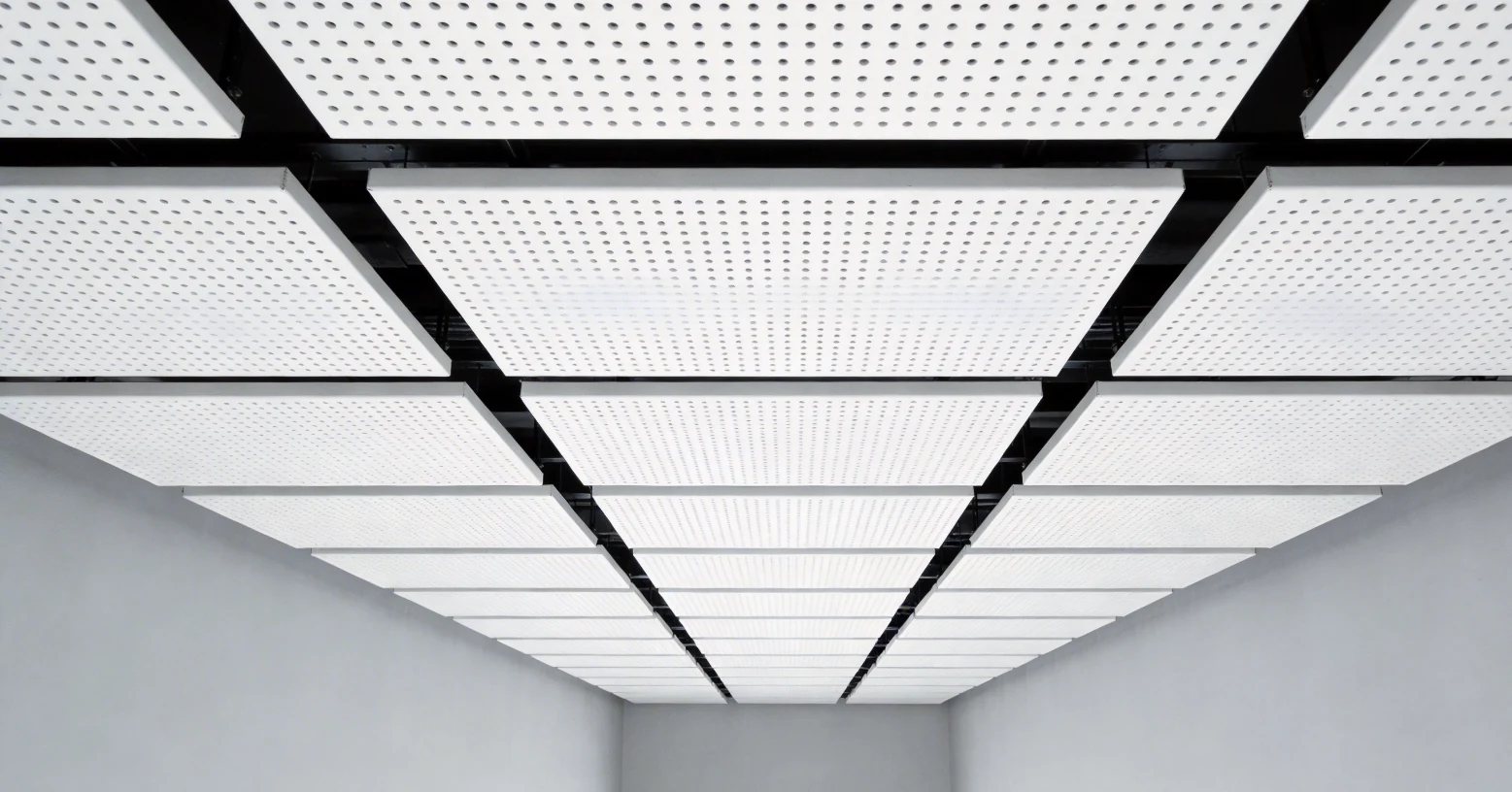
Perforations allow sound to interact with the material and cavity behind the face. Acoustic fleece and a separate absorbent infill are not simply two names for the same component. Their arrangement affects the assembly, so specify the backing product, its location and any additional infill separately.
When comparing acoustic reports, match the tested hole pattern, backing, infill and mounting conditions to the proposed ceiling. A test made with a different cavity or additional absorbent material cannot be assumed to describe an unbacked panel. The test report is evidence for an assembly, not a transferable rating attached to every panel with that hole size.
Also distinguish sound absorption within a room from sound transmission between rooms. An absorption rating such as NRC describes a different question from a ceiling attenuation rating such as CAC. A meeting-room privacy requirement cannot be answered by quoting only an absorption value.
Specify a pattern that the factory can reproduce
- Panel face dimensions and aluminum thickness.
- Hole shape, diameter and spacing in both directions.
- Square, staggered or other arrangement, with an orientation arrow where needed.
- Solid borders at edges, bends and service cut-outs.
- Finish, backing type and any infill or cavity requirement.
- Whether the open-area target applies to the field, panel face or another defined area.
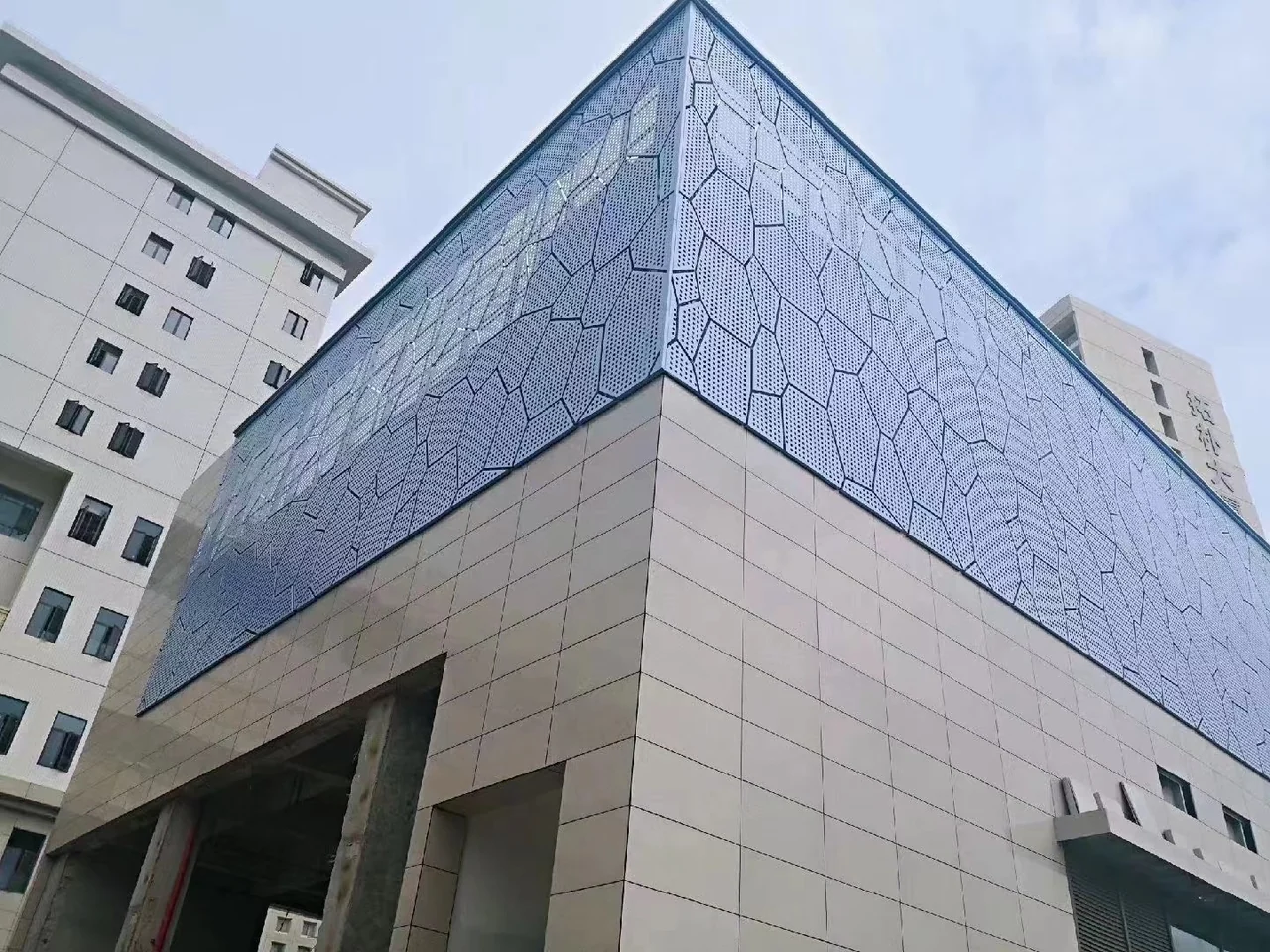
For decorative image perforation, a single diameter-and-pitch pair is not enough. The approved artwork, panel divisions and hole map must remain linked. Adjacent panels should carry an installation sequence so the image is not assembled in the wrong order.
Turn “20% perforation” into an unambiguous enquiry
Ambiguous: “600 mm acoustic panel, 3 mm holes, approximately 20% open.”
Defined geometry: “600 × 600 mm finished face; Ø3 mm round holes on a 6 × 6 mm square grid; 20 mm solid border on each edge; nominal field open area 19.6%; approximate whole-face open area 17.1% before additional openings.”
Complete that entry with the aluminum thickness, finish, backing product and acoustic assembly requirement. The geometry example does not assign an acoustic rating.
For the same square grid, the clear metal ligament between neighbouring holes is 6 − 3 = 3 mm. Changing to a 5 mm pitch leaves a 2 mm ligament and increases the nominal field open area to 28.3%. The hole diameter has not changed, but both the visual density and remaining metal have. Check the new pattern with the sheet thickness, bends and solid borders rather than substituting it only to reach an open-area target.
Draw a separate solid margin around light openings and access cuts. The repeating-field formula does not deduct these interruptions. For a final whole-face percentage, calculate the open-hole area from the production hole map and divide by the explicitly defined face area.
Approve a backed sample, not just a bare sheet
Review the pattern from the intended viewing distance with the proposed backing colour. Black backing can make holes appear darker than they do on an unbacked sample against a white wall. Check solid borders across two adjacent panels and show at least one typical light or grille cut-out.
For inspection, measure hole geometry, pitch and borders on the sample. Verify acoustic performance against the assembly test, matching the backing, infill and mounting build-up to the proposed installation.
Read the report beyond its single-number rating
Identify the test method and specimen construction before comparing the headline value. ASTM C423 measures absorption using a reverberation-room method; its result is not a room-to-room isolation test. Review the frequency-dependent absorption data alongside the stated rating, especially when the room has a specific acoustic problem rather than a general requirement to reduce reverberation.
Match the tested perforation, backing, infill, cavity depth, specimen size and mounting description to the proposed assembly. If the proposal removes the infill or changes the cavity, ask whether the existing report still covers that configuration. Do not label a bare decorative screen with the result for an absorbent-backed ceiling.
Separate panel performance from room coverage
A report for one ceiling assembly does not establish the acoustic outcome of a whole room. The amount and distribution of treatment, untreated walls, glazing, floor finishes and room volume all matter. Record the actual acoustically treated area after lights, solid service zones and access pieces have been accounted for.
For example, a 100 m² ceiling containing 18 m² of solid service panels leaves 82 m² of the specified perforated assembly before other exclusions. That is an area take-off, not a calculated NRC or a prediction of speech privacy. Give the acoustician the zone plan and complete assembly information so the room-level assessment uses the installed arrangement.
Check the first production panel against the hole map
- Measure hole size and pitch in both directions, including the staggered orientation.
- Check the first and last hole rows against each solid border and service opening.
- Inspect burrs and the finished opening after coating; very small holes need particular attention to coverage and bridging.
- Check backing continuity and attachment without obstructing required service access.
- Compare neighbouring panels so the pattern and solid margins align as intended.
What a useful acoustic-panel enquiry contains
For perforated aluminum panels, send the ceiling or wall layout, pattern drawing, face size, finish and backing requirement. State whether the goal is reverberation control, room-to-room privacy or a decorative screen. For image-perforated panels, add the artwork and viewing direction. This lets the quotation identify the actual construction instead of pricing a generic “acoustic aluminum panel.”