+86 180 2450 8117 info@lianhuicz.com Foshan, Guangdong, China
Lianhui / Aluminum Ceiling System

U-Shaped Baffle Ceiling

Product Features

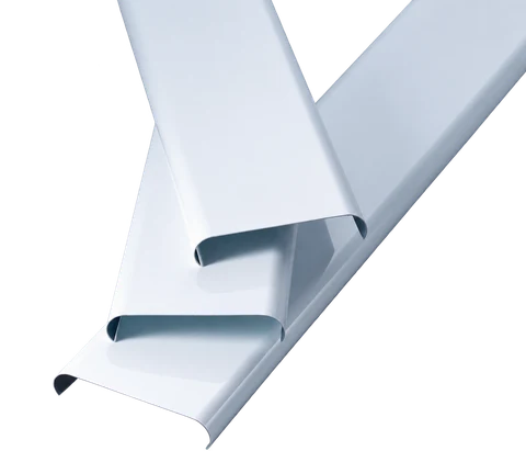
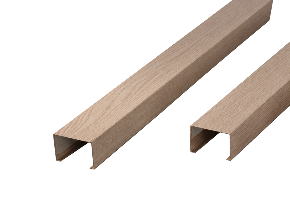
  • Folded U-shaped aluminum baffles form parallel open ceiling runs.
  • Horizontal-tooth and vertical-tooth carrier arrangements use different connection details.
  • Lengths are up to 6,000 mm, with spacing of at least 25 mm.
Cross-section shape
Folded open U-profile
Length
Up to 6,000 mm
Spacing
25 mm and above; adjustable to the layout
Carrier options
Matching horizontal-tooth or vertical-tooth carrier systems
  • Moisture resistance
  • Recyclable aluminum
  • Color retention*
  • Acoustic options*
  • Heat dissipation*
  • Lightweight & workable

*Color retention depends on the finish. Sound absorption requires a specified acoustic assembly; heat dissipation depends on the open or perforated layout.

Product Data

Specifications & Size Options

Technical overview
ItemSpecification
Cross-section shapeFolded open U-profile
LengthUp to 6,000 mm
Spacing25 mm and above; adjustable to the layout
Carrier optionsMatching horizontal-tooth or vertical-tooth carrier systems
Size and configuration options
Face width (mm)Height (mm)Thickness (mm)
25500.50–0.80
25800.50–1.00
251000.60–1.00
3050 / 60 / 70 / 73 / 800.50–1.00
30100 / 1200.60–1.00
301500.70–1.10
4050 / 60 / 800.50–1.10
401000.60–1.10
401200.80–1.10
40150 / 1800.90–1.10
5040 / 500.50–1.10
50600.60–1.10
50700.70–1.10
50800.80–1.10
5090 / 100 / 120 / 150 / 1800.90–1.10
100 / 120 / 150 / 16020 / 25 / 30 / 400.60–1.00
18020 / 25 / 30 / 400.70–1.00

Dimensions are in millimeters unless another unit is shown. Final sizes, finish and matching components are confirmed on the approved product schedule.

System Detail

Construction & Installation

U-shaped baffles with horizontal-tooth carriers

Horizontal-tooth U-baffle assembly — numbered English component reference
Enlarge drawing & English key

Reading the Drawing

The horizontal-tooth carrier locates the folded U-shaped baffles. Strip hangers connect this carrier to the main framework.

Numbered Component Key

Match each number to the label below. Dimensions shown on the drawing are in millimeters unless noted.

  1. M8 galvanized hanger rod
  2. 38/50 main-carrier hanger
  3. Horizontal-tooth carrier
  4. Strip-carrier hanger
  5. 38/50 main carrier
  6. U-shaped baffle
  7. Folded U-shaped baffle
  8. Galvanized hanger rod
  9. Height
  10. Base width
  11. Baffle height

Installation Steps

  1. Measure the finished ceiling elevation from the design drawings. Mark the level line and fix the perimeter angle along the walls.
  2. Establish the installation direction. Drill suspension points in the structural ceiling at no more than 1,200 mm spacing and secure the galvanized hanger rods with expansion anchors.
  3. Fit the main-carrier hangers and light-steel main carriers. Adjust their height and level, keeping the carriers parallel.
  4. Use strip hangers to connect the horizontal-tooth carriers to the main carriers. Level the secondary carriers; keep them parallel to one another and perpendicular to the main carriers.
  5. Fit the U-shaped baffles into the matching secondary-carrier clips, working in one direction.
  6. Measure perimeter panels on site, cut them to fit and support their edges on the perimeter angle.
  7. Keep hands clean during installation. Avoid sweat, oil and other contamination on the finished surface.

Combined U-shaped baffles with vertical-tooth carriers

Vertical-tooth combined U-baffle assembly — numbered English component reference
Enlarge drawing & English key

Reading the Drawing

The vertical-tooth arrangement uses a different carrier and a separate cover profile. Fit the baffles and covers in the illustrated order.

Numbered Component Key

Match each number to the label below. Dimensions shown on the drawing are in millimeters unless noted.

  1. M8 galvanized hanger rod
  2. Main-carrier hanger
  3. Vertical-tooth carrier
  4. Strip-carrier hanger
  5. Baffle cover
  6. U-shaped baffle
  7. Base width
  8. Folded U-shaped baffle
  9. Galvanized hanger rod
  10. 38/50 main-carrier hanger
  11. 38/50 main carrier
  12. Height
  13. Baffle height

Installation Steps

  1. Measure the finished ceiling elevation from the design drawings. Mark the level line and fix the perimeter angle along the walls.
  2. Establish the installation direction. Drill suspension points in the structural ceiling at no more than 1,200 mm spacing and secure the galvanized hanger rods with expansion anchors.
  3. Fit the main-carrier hangers and light-steel main carriers. Adjust their height and level, keeping the carriers parallel.
  4. Use strip hangers to connect the vertical-tooth baffle carriers to the main carriers. Level the secondary carriers; keep them parallel to one another and perpendicular to the main carriers.
  5. Clip the folded U-shaped baffles into the vertical-tooth carriers, then align and insert the cover profiles into the baffles.
  6. Measure perimeter panels on site, cut them to fit and support their edges on the perimeter angle.
  7. Keep hands clean during installation. Avoid sweat, oil and other contamination on the finished surface.
These system details explain the illustrated assembly. Anchor selection, structural capacity and final suspension spacing must follow the approved project drawings and local requirements. Different carrier configurations are not interchangeable.

Surface Finish

Solid-color and wood-grain finishes.

Typical Applications

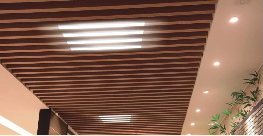
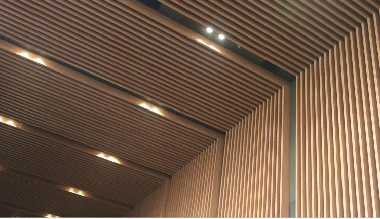
Public-building passages, airports, exhibition halls, shopping centers, stations and tunnel corridors.

A Closer Look

Product & Application Images

Project Enquiry

What to Include for a Quote

  • Ceiling plan and direction of the runs
  • Face width, depth, length and clear spacing
  • Finish and end treatment
  • Ceiling drop and positions of lights, sprinklers and air outlets
Request a Product Quote

Privacy settings

Browse with essential functionality only. This website does not currently run analytics, advertising trackers or embedded social widgets. Fonts are served by this website.

Essential functionality
Always available — navigation, enquiry security and your privacy preference.
Analytics & advertising
Not used. There are no optional trackers to enable.
External links
WhatsApp and other linked services open only when you choose their links. Their own privacy policies then apply.

This preference is stored in your browser, not sent to us. Leaving it unchecked does not enable tracking.

After a successful inquiry, a temporary confirmation cookie connects the submission to its thank-you page. It contains a random reference, not your contact details or drawings, and expires within 10 minutes or is cleared when used.

Read the Privacy Policy →