An aluminum panel shop drawing must describe a buildable part and its site interface: face, returns, openings, brackets, joints and revision. An elevation alone is not a manufacturing release. This guide separates module dimensions from finished faces and flat blanks, then works through datums, tolerances and approval responsibilities.
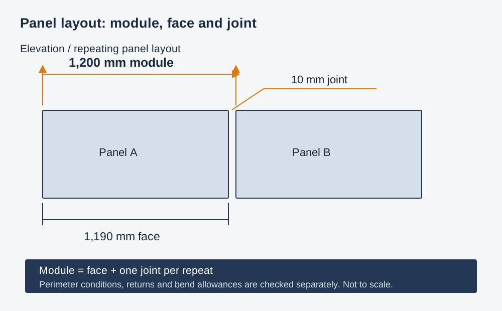
Separate the installed module, finished face and cutting blank
These are three different dimensions. The installed module describes the repeating layout. The finished face is the visible panel between joints. The cutting blank includes the material that becomes the folded returns, with allowances for bending.
| Drawing dimension | Example or definition | What it controls |
|---|---|---|
| Repeating module | 1,200 mm, measured between corresponding points on adjacent panels | Elevation setting-out and support coordination |
| Finished face width | 1,190 mm when one 10 mm joint is allocated to each repeat | Visible panel width; perimeter conditions are checked separately |
| Return depth | Dimensioned independently on the section | Edge geometry and clearance behind the face |
| Flat blank width | Developed from the finished section | Cutting; not simply the face plus two nominal returns |
This is a setting-out example, not a recommended joint width. Bend radius, sheet thickness and the forming method affect the developed blank. Supply the required finished geometry and agree who prepares the flat pattern; two parties using different bend allowances can produce different blanks from the same nominal section.
Give every hole and bracket a reference edge
Choose a clear datum, such as the lower-left corner of the finished face, and dimension openings from it. State whether dimensions locate hole centres, opening edges or fixing-slot centres. Show the slot direction as well as its length and width. A row of chained dimensions can hide an accumulated error at the last fixing; coordinates from a common datum make inspection easier.
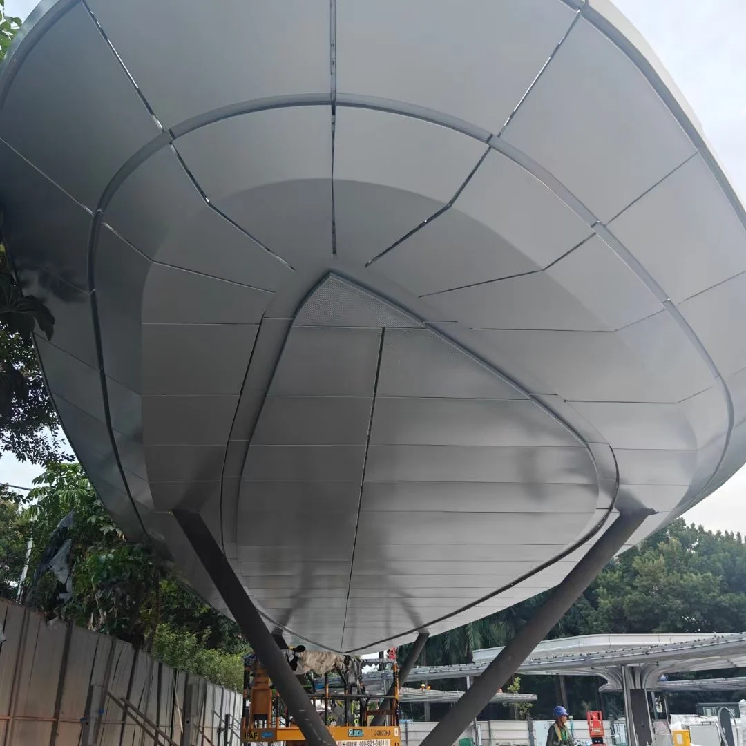
Include a face view, sections through the returns and a rear view for fittings. Label left-hand and right-hand parts separately. For a curved panel, state the radius reference—inside, outside or another defined surface—and identify the arc, chord and panel height without mixing them. Where a façade changes radius, use a panel-numbered model or a section for each geometry rather than one “typical” radius.
Draw the connection and the clearance it needs
A rear stiffener, an angle bracket and a support rail do different jobs. The stiffener controls local panel behaviour; the bracket connects the panel; the rail belongs to the supporting arrangement. Locate them together on the rear view so their positions can be checked against anchors, insulation and service openings.
At a corner, draw both adjoining panels and the joint between them. Show visible edges, sealant or joint strips where specified, and the route by which the installer reaches each fixing. A connection that can be drawn but cannot be reached after the next panel is installed needs its sequence resolved before manufacture.
For ceiling panels, mark which pieces must remain removable and what equipment is reached through them. A light cut-out does not establish how the light is supported. Show the separate support or the tested integrated detail, as applicable; do not leave the panel supplier to infer equipment loads from a symbol on the ceiling plan.
Use tolerances to protect fit, not as a single blanket number
Identify the dimensions that control fit: face size, squareness, return angle, hole position, curvature and bracket location. State the acceptance limit and measurement reference for each critical item. Flatness measured on an unsupported panel is not necessarily comparable with flatness measured on the installed assembly.
For adjacent shaped panels, a trial assembly can expose a mismatch that separate width measurements miss. Include the mating parts, joint spacers and relevant supports in the trial. Inspect the rear bracket engagement and fixing access alongside the visible face and joint alignment.
Worked tolerance example: four small errors at one fixing
Suppose a drawing locates four successive features at 250 ±1 mm from the previous feature. The nominal final position is 1,000 mm. At the worst-case limits, all four positive or negative errors can accumulate: 996–1,004 mm.
If the functional requirement is for the last hole centre to be 1,000 ±1 mm from datum A, dimension and inspect that coordinate directly. Do not infer it from four individually acceptable chain dimensions.
The ±1 mm values illustrate tolerance accumulation; they are not a general fabrication tolerance. Choose the permitted limits for the panel’s fit and confirm that the process can achieve them. A drawing that imposes both a chain and an overall dimension must state how the requirements relate, rather than leaving conflicting acceptance rules.
On the rear view, identify the viewing direction explicitly. A hole 80 mm from the left edge in a front view appears at the opposite side when the part is viewed from behind. Mark the same physical datum edge in both views to prevent mirror-image brackets on otherwise identical panels.
Link the drawing revision to the panel and its finish
| Field | Example entry or required information |
|---|---|
| Identification | Panel P-014, elevation E-02, drawing revision C, quantity 12 — illustrative identifiers |
| Material | Alloy, temper and nominal sheet thickness; do not enter overall folded depth as thickness |
| Geometry | Face, returns, corner treatment, openings, curvature and rear fittings |
| Finish | Process, retained sample code, gloss, grain arrow and exposed surfaces to coat |
| Inspection and packing | Critical dimensions, trial-assembly requirement, panel label and installation zone |
When a cut-out moves, revise the individual part drawing and the layout, not just the email attachment. Keep superseded drawings out of the production package. If only some panels change, list those panel numbers explicitly; otherwise a supplier cannot reliably distinguish a replacement drawing from an additional order.
Assign responsibility at each interface
Separate architectural appearance approval from structural connection design and fabrication release. The architect may approve the joint pattern while the facade engineer checks the support and fixing loads. The fabricator develops the part geometry, and the site team confirms surveyed interfaces. A single stamp reading “approved” should not leave those responsibilities unclear.
Record who owns the supporting-structure survey, anchor positions, bracket adjustment, joint movement allowance and final panel setting-out. The panel supplier cannot resolve an unknown site dimension by scaling a PDF. Mark dimensions awaiting survey as hold points and exclude affected pieces from the release schedule until resolved.
Release by panel ID, not by email date
Use a revision register listing the current drawing, affected panel IDs, quantity, finish and release status. When a revision changes only part of an elevation, list those pieces explicitly. Ask the factory to report whether they are uncut, formed, coated or packed before agreeing the change.
An editable model and its PDF should carry matching revision identifiers. If they conflict, stop the affected release and resolve which geometry governs. Do not let a newer PDF note silently coexist with an older cutting model. Closed-out comments should be incorporated into the issued drawing rather than remaining only in an email chain.
Use a short release checklist for every package
- Units, scale-independent dimensions and front/rear viewing direction are explicit.
- Panel IDs and quantities reconcile with the elevation and schedule.
- Material, thickness, finish and grain direction are identified.
- Returns, openings, stiffeners and brackets can be made and installed without clashes.
- Fit-critical tolerances, survey hold points and trial assemblies are resolved.
- Current drawings replace superseded production files for every affected piece.
For moving joints, add the installation temperature assumptions and connection movement strategy to the coordination package. The thermal-movement guide explains why a nominal joint width is not a complete movement detail.
What to send for a fabrication quotation
- A dimensioned PDF and the corresponding editable drawing or model.
- A panel schedule with quantities, installation zones and current revisions.
- The finished section, connection detail and any required trial assembly.
- The finish sample reference and grain direction.
- The inspection requirements, delivery sequence and separately identified spare panels.
For custom aluminum panels, send the most complex corner or curved piece with the typical panel. Those details reveal machining and assembly work that a total square-metre figure misses. The fabrication workflow explains where these drawing inputs are checked during production.