Reliable aluminum panel fabrication depends on controlled handoffs: the correct drawing becomes the correct blank, the formed geometry is accepted before finishing, and the finished panel stays identifiable through delivery. This guide follows cutting, forming, assembly, coating and inspection, with a worked production traveller and practical release checks.
Two fabrication routes, not one identical sequence for every panel
| Standard ceiling panel | Custom wall or shaped panel |
|---|---|
| Material selection → blank cutting → punching → leveling → corner notching → forming → clip-position punching | Sheet cutting → marking and corner cutting → bending or roll forming → specified welding → stiffener/bracket assembly → grinding and polishing → fabrication inspection |
Both routes produce an uncoated part ready for the selected finishing process. Operations are included where the design needs them: a plain panel does not require a decorative perforation operation, and a panel without welded joints does not need a welding stage. Precoated sheet requires a route that protects its existing finish during fabrication.
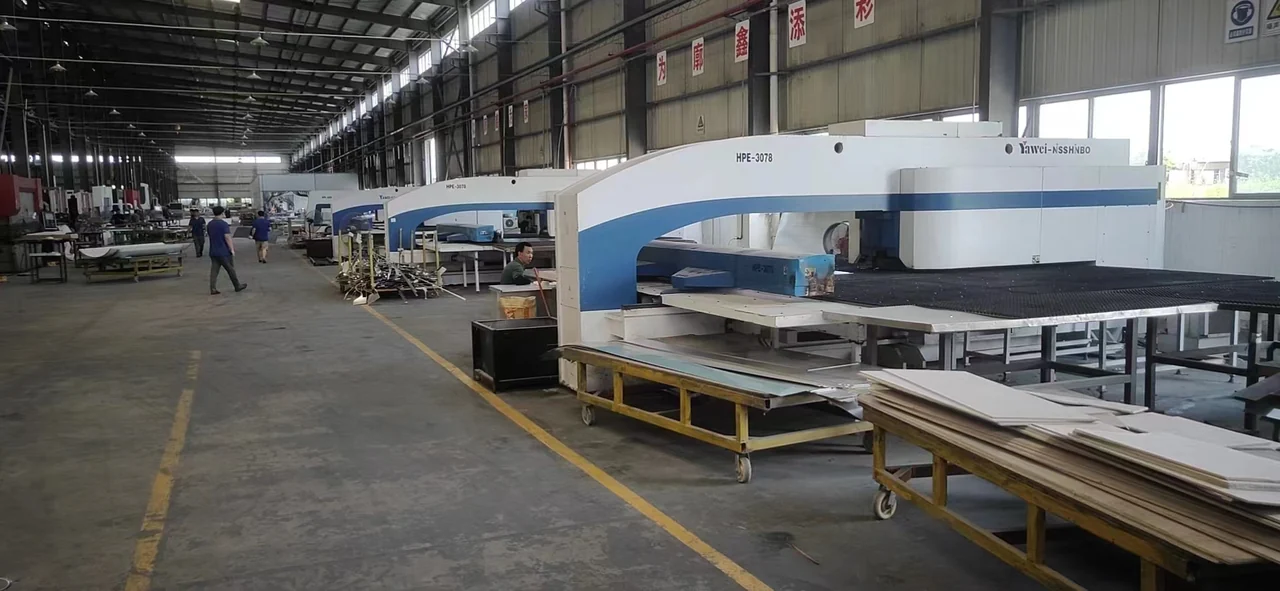
Cut and machine: establish the part number and geometry
The cutting list links the material, blank dimensions and quantity to a panel number and drawing revision. Incoming checks establish the alloy, temper, thickness and surface condition. At cutting, compare the blank dimensions and diagonals with the work instruction; this is the earliest practical point to detect the wrong material or an out-of-square blank.
Corner notches remove material so adjoining returns can be formed. Punching produces holes, slots and perforation patterns. Keep service openings and fixing holes tied to the same reference edges used on the shop drawing. A correctly sized opening in the wrong position is still a nonconforming part.
Form: distinguish straight bends from curved sections
A press brake forms straight returns. Roll-forming equipment produces the required curved section. The work instruction should identify the finished dimensions, return angles and radius reference so the operator and inspector measure the same geometry.
Forming can affect features near a bend. Review holes and notches close to the return during drawing preparation, including the required bend relief and tool access. Where a critical feature must remain accurately located after forming, agree its machining sequence with the fabricator.
For curved sections, check the specified radius or template, panel height and mating edges before coating.
Assemble and finish the joints before coating
Fit the specified stiffeners, brackets and connecting parts to the rear of the panel. Their positions must agree with the supporting layout and leave access for installation. Complete the welds required by the design, then grind and polish the worked areas to the specified surface condition.
Use a trial assembly for adjoining shaped components or critical corners. Check the fit, joint width, face alignment and access to fixings. Trial assembly is particularly useful where several individually acceptable dimensions combine into one visible joint.
A changed bracket position must be recorded on the drawing and panel schedule. Keeping that revision visible prevents a correctly fabricated panel from being delivered with an obsolete connection detail.
Follow one panel through the production record
A production traveller is the record that stays linked to a part as it moves between operations. Below is an illustrative folded panel, P-014, for a 1,200 × 600 mm repeating layout with 10 mm joints. Its finished face is 1,190 × 590 mm; its 25 mm returns are dimensioned separately. These dimensions illustrate record-keeping, not a standard panel specification.
| Operation | Information used | Release record |
|---|---|---|
| Blank cutting | Approved developed pattern for the selected sheet, bend radius and tooling | Material identity, blank length/width and quantity. Do not cut from the face dimensions. |
| Punching / notching | Hole coordinates, corner reliefs and panel orientation | First-piece hole locations and orientation checked against revision C. |
| Forming | Finished face 1,190 × 590 mm; 25 mm returns; drawing angles and tolerances | Measured face, returns and diagonals recorded after bending. |
| Rear assembly | Bracket drawing and supporting-rail locations | Bracket positions and access checked; trial fit where specified. |
| Coating release | Accepted geometry, surface preparation and finish F-07 | Part identity and finish code carried into the coating batch. |
| Packing | Zone E-02 layout and panel schedule | P-014, revision C, quantity and package number reconciled. |
If a hole moves in revision D, identify affected P-014 parts at every stage: uncut material, punched blanks, formed parts and finished stock. Do not issue the new drawing only to the next operator while earlier parts continue through the old route.
Prevent a hole near a bend from becoming a distorted opening
The material around a bend deforms during forming. A hole or slot too close to that region can stretch or tear; a relief cut separates a local return from adjoining material that must remain flat. Resolve the hole-to-bend relationship, relief shape and machining sequence before releasing the cutting pattern. The required distances depend on the material and bend geometry.
For a critical fixing hole, inspect its final position after forming, not only its position on the flat blank. A punched blank can be correct while the finished fixing is no longer round or correctly located.
Pretreat, apply the finish and cure it
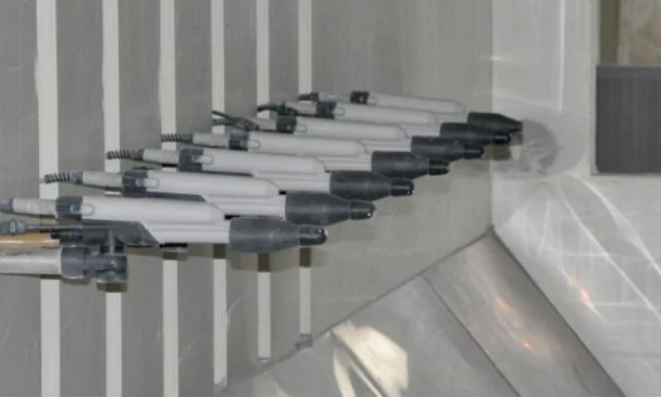
For a post-coated panel, the accepted fabricated part is cleaned and degreased, rinsed, chemically pretreated and dried. The pretreatment must suit the selected coating and substrate. The panel is then hung, coated, cured and cooled before inspection and handling.
Liquid paint is atomized and sprayed; powder is deposited electrostatically and then cured. Follow the coating supplier’s application and curing requirements. Oven settings and elapsed time are not interchangeable with an approved cure schedule for the actual workpiece and coating.
Use inspection gates with a defined release decision
| Gate | Check | Record or action |
|---|---|---|
| Before machining | Material identity, thickness, drawing revision, blank size and quantity | Match the material and cutting list to the work order |
| Before coating | Face dimensions, squareness, returns, openings, curvature, fittings and worked joints | Hold nonconforming parts for disposition; record critical trial assemblies |
| After coating | Appearance, coverage and the specified coating properties | Compare with the retained sample and inspection requirements |
| Before packing | Panel numbers, quantities, direction marks and protection | Reconcile each package with the packing list and installation zone |
Keep dimensional results and surface-test results separate. A good colour match does not resolve an incorrect fixing position. Equally, a dimensionally correct panel should be held if its finish has unacceptable runs, bubbles, contamination or damage.
Approve the first piece before repeating the batch
A repeated panel error is more expensive than a single rejected first piece. Identify the critical dimensions on the work instruction and inspect a representative part after the last operation that can change them. For a folded panel, that means checking the finished section, not accepting only the flat blank.
Material springback affects the angle after tooling pressure is released. Changes in sheet properties, tooling or bend radius can therefore require a setup adjustment even when the programmed angle is unchanged. Agree the finished angle and measurement condition; do not use the machine setting as the acceptance result. Recheck the first piece when a material lot, tool setup or drawing revision changes.
Keep a nonconforming panel out of the next operation
Use a hold record containing the panel ID, revision, affected dimension or surface, measured result and proposed disposition. A coating operator should not receive a bent panel that is still awaiting a decision on its geometry. Once the visible finish is applied, correction may involve both refabrication and refinishing.
Separate the available dispositions: remake, approved rework, or a formally accepted deviation. The person responsible for the affected interface must approve a deviation before release. “Installer can adjust on site” is not a defined disposition when it changes the fixing, joint width or visible alignment.
Build a handover pack the site team can use
- Current installation layout and panel schedule, with left/right-hand pieces distinguished.
- Package-to-panel index so each crate can be assigned to an installation zone.
- Inspection records for agreed critical features and closed-out deviations.
- Finish identification, handling guidance and separately labelled spare pieces.
Before a phased shipment leaves, reconcile the released quantity against the latest schedule. A missing corner panel can delay a complete bay even when most of its area has arrived. List outstanding special pieces explicitly instead of reporting delivery progress only as a percentage of square metres.
Pack for installation order as well as transport
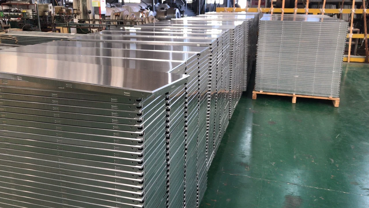
Protect decorative faces, support vulnerable edges and restrain panels against movement in the package. Label the specification, colour, batch, quantity and installation direction where relevant. Grouping by installation zone helps the site team find the right panels without repeatedly unpacking unrelated pieces.
After final inspection, identify panels on the packing list and protect faces, edges and corners against handling damage.
For a manufacturing enquiry, provide the shop drawings and panel schedule, finish approval, required inspection records and delivery sequence. The manufacturing page shows the equipment and full workflow; the coating comparison explains the finish choices.