Choose a clip-in ceiling by its complete panel-and-carrier section, not its face size alone. High-edge and low-edge panels can look similar from below while engaging different concealed supports. This guide compares the ranges, explains replacement surveys and identifies the access and service details to settle before ordering.
What 20, 25 and 30 mm actually describe
These numbers describe the height of the folded panel return, not the aluminum sheet thickness and not the total ceiling drop. The drop also has to accommodate carriers, hangers, services and the clearances needed for the selected assembly. Replacing a 25 mm return with a 20 mm return does not automatically reduce the required ceiling void by 5 mm.
| Module | High-edge return / sheet | Low-edge return / sheet |
|---|---|---|
| 300 × 300 | 25 / 0.50–0.70 | 20 / 0.35–0.70 |
| 600 × 600 | 25 / 0.50–1.00 | 20 / 0.40–1.00 |
| 600 × 1,200 | 25 / 0.65–1.10 | 20 / 0.65–1.10 |
| 400 × 1,200 | 30 / 0.70–1.20 | 20 / 0.70–1.20 |
| 600 × 2,400, square edge | 25 / 1.20–1.50 | 20 / 1.20–1.50 |
A separate 30 mm high-edge series is also available in 600 × 600, 600 × 1,200 and 300 × 1,200 mm formats. Identify that series explicitly rather than changing the return on a standard panel description. The table gives ordering options; it is not a span table or a statement that the thinnest option suits every installation.
Why a taller edge is not automatically a better ceiling
The return forms part of the panel section, but performance also depends on face dimensions, sheet thickness, perforation, engagement and support. The two 600 × 1,200 mm ranges above have the same listed sheet-thickness range even though their returns differ. It would be misleading to rank them only by the labels “high” and “low.”
The high-edge detail uses its specified concealed carrier arrangement; the low-edge detail uses triangular carriers. Check the engaged edge, not just the overall height. A replacement panel with the right face dimension can still sit incorrectly or fail to engage because its return geometry differs.
For a new ceiling, select the panel and supporting system together. For an existing ceiling, use a removed panel and a carrier section to establish compatibility. Do not force a nearly fitting edge into place or trim the clip edge to make an unrelated panel fit.
Plan the grid around services and perimeter cuts
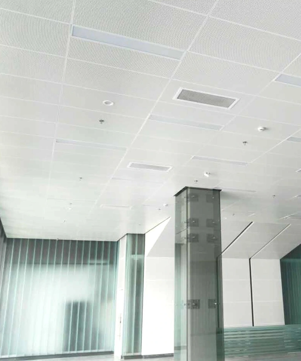
A reflected ceiling plan should show full panels, perimeter pieces, lights, air outlets and access locations. Start by deciding which lines need to align: a central lighting row, a corridor axis or the edge of a wall. Then distribute the remaining edge pieces deliberately instead of allowing the last row to become a narrow sliver.
Service openings need both a face location and a support detail. Equipment should not be assumed to hang from a cut panel simply because its outline fits inside a module. Coordinate the independent support or approved integrated arrangement before panel manufacture.
Use an assembled sample to answer the practical questions
- Joint alignment: place adjoining panels on the proposed carriers and inspect the visible joint, corners and face levels.
- Engagement: confirm the specified edges seat correctly without visible deformation.
- Removal: demonstrate the intended release method and the clearance needed around lights, walls or access equipment.
- Reinstatement: return the panel to the same position and inspect whether the joint and face alignment remain correct.
- Finish: compare plain and perforated samples under the proposed lighting if both occur in the same ceiling.
Approve colour on the finish sample and engagement, removal and joint alignment on the assembled sample. For a refurbishment, retain an identified spare panel and its carrier reference for future replacement orders.
Diagnose visible defects before replacing panels
| What you see | What to check first |
|---|---|
| One panel sits below adjacent faces | Whether its edges are fully engaged, whether the panel is the correct series, and whether the local carrier is level |
| Joints wander across a row | Carrier alignment, module setting-out and consistent panel orientation |
| A panel cannot be removed at a service point | Removal method, edge type, surrounding clearances and the equipment access plan |
| Visible surface distortion | Panel handling damage, forcing during installation, support arrangement and specified module/thickness combination |
Record the location and inspect the assembly before deciding the cause. These symptoms can have more than one explanation; changing the return height alone is not a repair strategy.
Replacement example: the same face does not mean the same panel
Consider two 600 × 600 mm panels, each made from 0.70 mm aluminum. One has a 25 mm high-edge return; the other has a 20 mm low-edge return. Both descriptions fit the listed dimensional ranges, but they identify different concealed connections. Buying by face and sheet thickness alone leaves the most important replacement detail unspecified.
| Item | How to identify it |
|---|---|
| Existing panel | Mark its location and orientation; measure the face, return height and sheet thickness separately. |
| Engagement | Record the complete edge section and carrier shape, including the contact surfaces. |
| Finish | Retain a cleaned sample and record colour, gloss, perforation and backing. |
| Trial replacement | Fit one compatible sample with adjoining panels, then demonstrate removal and reinstatement. |
If one corner remains proud, inspect the return and local engagement before pressing harder. If several adjacent panels step together, inspect the supporting plane as well as the individual panels. Photograph the location before removing parts and keep the observations linked to the survey sheet. This distinguishes an isolated damaged edge from a repeated setting-out or support problem.
Draw the access envelope above and below the panel
A removable panel needs more than an opening in plan. Show the movement required to release the edge, the space to lower or turn the panel, and the route for an operative to reach the equipment. A pipe immediately above the carrier or a pendant light immediately below the panel can prevent removal even when the nominal module fits.
Use the selected system’s removal procedure in the mock-up. Do not borrow the tool or release direction from another clip-in or clip-on product: manufacturers use different retention arrangements. At handover, identify access panels and provide the compatible removal tool and instructions where required.
Coordinate equipment and ceiling restraint separately
Record the dimensions and weight of luminaires, air outlets and access equipment. A panel cut-out only defines the opening; it does not prove that the panel or carrier can support the equipment. Use independent support or a specifically designed and approved integrated detail, as required by the project.
Check perimeter restraints, suspension and seismic requirements against the applicable project design. Do not take a test for another manufacturer’s complete ceiling as evidence for a locally assembled mix of panels and carriers. The accepted submission must identify the actual components and their arrangement.
A practical installation and handover sequence
- Check setting-out lines, services and the support plane before closing the ceiling.
- Install a representative bay containing a perimeter, a service opening and an access panel.
- Inspect engagement, joint alignment and face levels without forcing mismatched edges.
- Demonstrate safe removal and reinstatement, then identify the approved arrangement in the installation record.
- Provide labelled spares that match the face, return, carrier and finish, not only the nominal module.
Order by series, section and complete schedule
Send the selected high-edge or low-edge series, module, return, sheet thickness and edge version. Include the ceiling plan, carrier and suspension detail, finish, perforation, backing and spare-panel quantity. If sound absorption matters, use the acoustic specification guide to define the complete assembly rather than adding “acoustic” to the panel name.