Select an aluminum strip ceiling by the visible joint, installed pitch, carrier connection and maintenance access. C, G, S, U and hook-on profiles are not interchangeable simply because their face widths match. This guide compares the sections and converts the choice into a coordinated layout, cutting schedule and complete quotation.
Compare the actual section dimensions
| Profile | Face width → edge height | Sheet thickness by width | Joint and connection |
|---|---|---|---|
| C | 100 / 150 / 200 / 300 → 15 | 100–150: 0.40–0.70; 200: 0.45–0.80; 300: 0.60–0.90 | Low beveled edges; individual strips engage carrier teeth |
| G | 100–150 → 11; 200–300 → 15 | 100–150: 0.40–0.70; 200: 0.45–0.80; 300: 0.60–1.00 | Recessed joint and dedicated G carrier |
| S | 300 → 29 | 0.70–0.95 | Deep square or beveled edge; select the matching version of the carrier |
| U | 85 → 15 | 0.5 or 0.6 | Straight or inclined arrangement, each with its own carrier |
| Hook-on | 150 → 20; 200 → 25; 300 → 29 | 150: 0.50–0.70; 200: 0.60–0.80; 300: 0.70–1.00 | Adjacent folded edges interlock and engage a hook-on carrier |
These dimensions identify available sections, not load capacities. Lengths are offered up to 6,000 mm in these families, but the order length must also suit the room, support arrangement, access route and handling plan. A long uninterrupted strip can reduce end joints while making replacement and movement through a finished building more difficult.
Face width is not necessarily the installed pitch
Face width is the visible width of the strip. Installed pitch is the distance between corresponding points on successive strips, including the intended joint or opening. Use the confirmed pitch to set out the ceiling and the face width to identify the product. Do not add a joint allowance to a module dimension that already includes it.
Setting-out example: a 2,400 mm zone divided into a confirmed 100 mm installed pitch contains 24 repeats. At a confirmed 150 mm pitch it contains 16. This arithmetic says nothing about whether the end strips need trimming: wall alignment, perimeter details and the layout start point still determine the final edge pieces. It is a planning example, not a claim that every 100 mm face installs on a 100 mm pitch.
Set out lighting rows, air outlets and access positions on the same reflected ceiling plan. A strip selected in isolation may create narrow perimeter pieces or place a joint through the centre of a light. Adjust the layout before making the cutting schedule.
Choose the joint appearance, then prove the carrier fit
C strips suit a closely spaced linear joint. G strips introduce a more pronounced recessed joint. S strips have a deeper return, with square and beveled edge versions. U strips allow the selected straight or inclined arrangement. Hook-on strips use connected folded edges rather than relying only on a similar-looking face.
Ask for a short assembled sample containing at least two adjacent strips and their carrier. View it from below, then inspect the connection from the side. This is more informative than a loose finish sample: it shows the joint, alignment and how the edges actually engage.
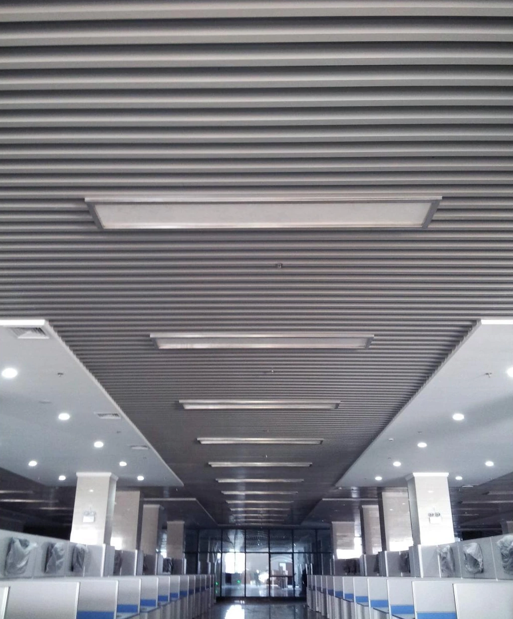
Worked layout: centre a strip field inside a 2,500 mm zone
For a confirmed installed pitch of 150 mm, sixteen repeats occupy 16 × 150 = 2,400 mm. A 2,500 mm setting-out zone leaves 100 mm, or 50 mm at each side for a centred layout.
Draw the two 50 mm perimeter zones as actual details: a closure, border or approved cut piece. Do not simply call them “half strips”; 50 mm is not half of this 150 mm repeat.
Use the clear dimension between the chosen setting-out boundaries, not a rough structural opening. If perimeter trims occupy part of that width, deduct their agreed geometry before repeating the calculation. Confirm that the final edge treatment retains the panel correctly and allows the selected removal method.
| Section | S-Shaped Ceiling, deep square edge; matching square-edge carrier |
|---|---|
| Dimensions | 300 mm face, 29 mm edge, 0.80 mm nominal aluminum sheet |
| Cutting schedule | List each required length and quantity from the coordinated ceiling plan |
| Finish and access | Plain face; selected finish code and grain direction if applicable; access strips identified on plan |
The example selects 0.80 mm within this S-profile range. It does not establish support spacing or load capacity. Those belong to the coordinated ceiling assembly, including carriers and suspension.
Test maintenance access before choosing long strips
Mark the valves, dampers, cable junctions and other items that need access. Then show which strip or access panel is removed to reach each one. “Removable” is incomplete unless the removal direction, tool access and space to handle the released component are understood.
C and G strips in this range permit individual removal; S strips can be removed within the ceiling field. The actual edge and retaining arrangement still matter. At handover, demonstrate removal and reinstatement on the supplied system rather than assuming that a method used on another manufacturer’s ceiling will work.
For a replacement order, provide the installed face, a dimensioned edge section and a carrier sample or drawing. Match the engagement geometry and joint appearance before manufacturing the replacement strips.
Convert ceiling area into an orderable cutting schedule
Area is useful for budgeting, but the factory needs lengths and quantities. Start with the installed pitch, count the rows, and split each row into the agreed stock or cut-to-length pieces. Identify end joints, perimeter closures and access strips separately. A single waste percentage cannot explain where offcuts arise or whether they can be reused.
As a simple take-off, sixteen rows each containing one 4 m strip require 64 linear metres of strip. If the confirmed pitch is 150 mm, those repeats cover a nominal 2.4 × 4 m field, or 9.6 m², before perimeter detailing. Carriers, hangers, end treatments and spare strips remain separate items. This example assumes one continuous piece per row; a divided installation needs a joint and piece-count schedule.
Coordinate end joints with lighting and maintenance
Show where long strips stop or join and how that joint is supported. Aligning all end joints produces a different appearance from a staggered arrangement. Confirm the chosen detail on a sample bay and keep the sequence visible on the reflected ceiling plan.
For long strips, check the delivery route and the space to remove a replacement after the building is occupied. A piece that could enter an open construction floor may not pass through the finished corridor or lift. Divide lengths deliberately where access demands it, while coordinating the resulting end joints and carriers.
Check five items before releasing the order
- Correct profile and edge version, with the matching carrier.
- Confirmed installed pitch and perimeter treatment.
- Length-by-length quantities, separate spares and the end-joint arrangement.
- Lights, air outlets and removable service zones on the same layout.
- Finish direction and protective handling instructions for the selected surface.
Compare quotations on the whole ceiling, not just the strip
| Package | Compare on the same basis |
|---|---|
| Visible strips | Exact profile, sheet thickness, lengths, finish and plain or perforated face |
| Supporting parts | Matching carriers, connectors, hangers and perimeter pieces; clarify exclusions |
| Special pieces | End joints, service openings, removable access areas and inclined sections |
| Quantities | Installed area versus ordered strip lengths; offcuts and spares listed separately |
Finish and acoustic backing are separate decisions. A perforated face should be specified with its pattern, solid borders and backing, as explained in the perforation and acoustics guide. For the edge sections and dimensions, compare C, G, S, U and hook-on product details before requesting the complete ceiling package.